Used to drill out holes to optimal size to improve ease of assembly
Tools
N/A
3.3mm drill bit
1
1
3.5mm ok if you can’t get 3.3mm
Tools
N/A
2.6mm drill bit
1
1
2.5mm ok if you can’t get 2.6mm
Tools
N/A
2mm drill bit
1
1
Tools
N/A
AA Battery
4
1
Used to power the Radio Transmitter
Tools
N/A
Heat Gun or Lighter
1
1
Used to heat the heatshrink
Tools
N/A
Filament Dryer or Modifed Food Dehydrator
1
1
Used to dry TPU filament during printing
Tools
N/A
PVA Glue
1
1
Tools
N/A
OPTIONAL: Hacksaw
1
1
Used for cutting 6mm steel rods (not required for V3D kit)
Tools
N/A
OPTIONAL: Blue Loctite
1
1
Used to help keep flange grub screws in place
Tools
N/A
OPTIONAL: Multimeter
1
1
For switch continuity, alternative methods easily possible.
3D Printed Parts for Deathracer
Assembly
Name
Qty
Colour
Note
Front Frame/Front Body
ArmFrame.stl
1
A
Front Frame/Front Body
BracketA.stl
1
B
Front Frame/Front Body
BracketB.stl
1
B
Front Frame/Front Body
DriveConsole.stl
1
B
Front Frame/Front Body
FrontFrame.stl
1
B
Front Frame/Front Body
FrontGrill.stl
1
A
Front Frame/Front Body
LeftDriveLever.stl
1
A
Front Frame/Front Body
LeftHeadlight.stl
1
A
Front Frame/Front Body
LeftServoArm.stl
1
B
Front Frame/Front Body
RightDriveLever.stl
1
A
Front Frame/Front Body
RightHeadlight.stl
1
A
Front Frame/Front Body
RightServoArm.stl
1
B
Front Frame/Front Body
ServoFrame.stl
1
B
Rear Frame/Rear Body
FinDetail.stl
1
A
Rear Frame/Rear Body
MainFin.stl
1
B
Rear Frame/Rear Body
RearFrame.stl
1
B
Rear Frame/Rear Body
RearjetA.stl
1
A
Rear Frame/Rear Body
RearJetB.stl
1
A
Rear Frame/Rear Body
RearPanel.stl
1
B
Rear Frame/Rear Body
RearPanelGrill.stl
1
A
Rear Frame/Rear Body
Seat.stl
1
A
Rear Frame/Rear Body
SeatBase.stl
1
A
Rear Frame/Rear Body
TopFin.stl
1
A
Bludger
BoomFrame.stl
1
B
V3D Modified Design Available
Bludger
Smacker.stl
1
B
V3D Modified Design Available
Two Part Chassis (2 part frame)
MAIN_FRAME_2PART_LOWER.stl
1
B
Two Part Chassis (2 part frame)
MAIN_FRAME_2PART_UPPER.stl
1
B
Pro Drive
DriveGear.stl
2
A
R/L identical
Pro Drive
WheelA.stl
2
A
R/L identical
Pro Drive
WheelA1.stl
2
A
R/L identical
Pro Drive
WheelB.stl
2
A
R/L identical
Pro Drive
WheelB1.stl
2
A
R/L identical
Pro Drive
ProMotorFrame.stl
2
B
R/L identical
Pro Drive
LProMainFrame.stl
1
B
Pro Drive
RProMainFrame.stl
1
B
Pro Drive
TrackV2
60
A
Pro Drive
Gearbox Spacer
2
B
User Modification Part
Rider
HeadMech.stl
1
A
Rider
LBicep.stl
1
A
Rider
LForeArm.stl
1
A
Rider
LInsert.stl
1
A
Rider
LShin.stl
1
A
Rider
LThigh.stl
1
A
Rider
RBicep.stl
1
A
Rider
RForeArm.stl
1
A
Rider
RInsert.stl
1
A
Rider
Face
1
Mixed
V3D Modified Design Available
Rider
RShin.stl
1
A
Rider
RThigh.stl
1
A
Rider
SideL.stl
1
A
Rider
SideR.stl
1
A
Rider
Hip.stl
1
B
Rider
ElbowI.stl
2
B
R/L identical
Rider
ElbowO.stl
2
B
R/L identical
Rider
LFoot.stl
1
B
Rider
LGaunlet.stl
1
B
Rider
LKnee.stl
1
B
Rider
LShoulder.stl
1
B
Rider
MainBody.stl
1
B
Rider
MainHead.stl
1
B
Rider
RFoot.stl
1
B
Rider
RGaunlet.stl
1
B
Rider
RKnee.stl
1
B
Rider
RShoulder.stl
1
B
3D Printing Guide
Files
For the files, you can currently only get these from Michael Baddeley on Pateron. You can sign up on the $1 tier, then access the onedrive link on the about page, and download the whole thing or just the deathracer section.
The parts you need to print are all shown in the printing section of Bill of Materials
Materials
For the the filament, I’d recommend ABS if possible. Since this is a combat robot it’ll benefit from the durability and impact resistance. PETG and PLA are quite strong, but also quite brittle under impact making them less ideal, but easier to print if you have an open printer.
You’ll likely want a primary and secondary colour in whatever material you choose although you could do it all in one colour if you want, or even paint it afterwards. The Bill of Materials also shows you which parts to print in what colour.
The component you have less material choice on is the tracks. Extremely high durability is needed here, so really the only option is TPU, which will also provide fairly decent grip on many surfaces.
TPU comes in a few different varieties in terms of their hardness and there’s also a foaming type. You want to avoid both the soft, and foaming TPU since we don’t want the tracks to be stretchy. If they stretch too much they are more likely to come off as you drive around, which obviously you don’t want.
At my recommended settings, you’ll use about 600g.
TPU will need to be dried constantly as it prints so you’ll need a filament dryer or a modified food dehydrator to do this. Printing TPU can be hard so I recommend trying just a couple of tracks on the bed at a time initially to reduce the impact of any potential waste in the event of print failure.
Print Settings
In terms of print settings in general, you don’t need to modify anything too much away from your standard settings, just remember that walls contribute more to strength than infill.
I used the same settings for all my ABS parts as its just simpler but if you want to be more economic with your filament you can reduce the settings for anything on the bodywork or rider.
I recommend 6 perimeters, 6 top and bottom layers and 25% infill. Reduce to 3-4 perimeters, 4 top and bottom and 15-20% infill for the rider and body/frame if desired.
For the tracks, I have some special recommendations because if the tracks stretch too much they are more likely to come off and jam. Change the infill to be grid pattern, and change the infill angle so that there are straight lines from one hole side to the other. Also reduce the scale to 99.5% to shorten the overall length of the tracks and increase tension.
By all means use less material if you want, these are just recommendations.
Assembly video
Deathracer Written Assembly Guide
Electronics Preparation
Printing takes quite a while so while your machines are working you can get on with the next section, some electronics prep.
One piece of advice before we go into it, never turn your Deathracer without the transmitter turned on and never turn off the transmitter until AFTER the battery is disconnected. In light of that, let’s START by pairing the receiver to the transmitter.
Pairing
Pairing makes the connection between your transmitter and receiver so the receiver knows where to receive signals from.
To do this you’ll need the jumper cable which is included with the receiver, and you’ll need a power source for the receiver.
To power the receiver you can use any 5V source, but if you check the wiring diagram, you’ll see that we can just use an ESC to do this as it has a BEC or Battery Eliminator circuit, which converts the battery voltage to 5V.
Connect the pairing jumper to the batt/vcc connector of the receiver
Connect any channel on the receiver to the BEC cable of an ESC.
Connect the LiPo battery to the ESC.
Turn on the BEC to send power to the receiver
Hold down the bind button on the transmitter as you turn it on.
The transmitter will automatically bind to the receiver.
Turn off the BEC circuit, then everything can be disconnected.
Test the circuit by removing the jumper, move the BEC wire to the VCC connector of the receiver, and plug in a basic servo to channel one or two.
Turn on the transmitter, turn on the BEC.
You can now control the servo from the transmitter.
Job done.
Transmitter Mixing
If you have tested your receiver with a servo, you’ll likely have realised that one control on the transmitter controls one channel on the receiver. But to make the Deathracer go forwards we need two ESCs on two separate channels to go forward together. To do this we have to mix the two channels together which allows us to send a proportion of control on one channel over to another, from -100% to +100%.
Turn on the transmitter
Hold down the ok button to open the menu
Select functions,
Go down all the way to mixes
For mix 1
Set to ON
Set master to 1
Set slave to 2
Pos. mix to 100%
Neg mix to 100%
Offset to 0%
Go to mix 2
Set to ON
Set master to CH2
Set slave to CH1
Set pos mix to -100%
Set neg mix to -100%
Set offset to 0%
Once the two mixes are set, HOLD the cancel button to save and go back.
Optionally, reopen the mixes to double check it saved correctly, press cancel to close
Battery Divider Harness
The next thing we can do is create our battery splitter harness. The kit has this included so no need to make another, this instruction is for any self sourcers.
For the sake of clarity – DO NOT modify the battery in anyway, at any time.
Now, lets make the splitter harness.
Cut 4 100mm length of 12AWG wire, two red two black.
Strip about 3mm off the ends
Tape the black wires together at one end, and do the same with the red.
Add solder to all the tips.
Add solder to the wire side (without springs) of the MALE connector.
The solder the red wires to the terminal marked with + and black to the terminal marked -.
Remove the tape carefully and avoid cutting the wires
ONCE COLD, slide heat shrink over the ends and onto the terminals. Heat using heat gun or lighter to cover the connections.
Now add heatshrink to each of the individual wires
Tape them back to keep them out the way while doing the next steps.
Now using the FEMALE connectors, connect one black and one red wire to each. Again, observe the + and – markings on the connector.
Once cold, slider over the heatshink and shrink it.
The final result should look like this.
Head Switch and ESC
The switch at the base of the rider’s head is how the deathracer is disabled in combat. When this switch is in the off position the BEC (battery elimination circuit) on the electronic speed controller (ESC) turns off and no longer sends power to the receiver or motors effectively killing the racer.
The intention here is to add 20-30cm of wire and a locking connector to the switch and ESC so that it can be connected and disconnected as needed but will not come loose during racing.
The kit comes with a JST type pair of wires which we will use to do this.
I’ve suggested a soldering method rather than crimping as I felt it was probably more accessible but if you have the tools and terminals, feel free to just crimp new terminals on the wires.
The included harness should be about 30cm long. Cut it so that the male end is about 20cm long, and the female end is about 10cm long.
Strip the ends and solder the long length to the switch, it doesn’t really matter which way around.
The short length will be connected to an ESC. Cut the switch off the esc, close to the switch to leave maximum cable length on the ESC.
Strip the wire ends on the ESC and short wires, slip about 20mm of heatshink onto the wires and slip it down to the end away from the stripped ends.
Solder red to red and black to black.
Once cool, slip the heat shrink over and heat.
The ESC and switch should now connect up easily.
Head Switch Orientation
The other thing to do with the switch is check which way is on, and which is off. This will be important later on. Sometimes this is marked on the body, but often isn’t. The notch on the thread is also not consistent so if you are unsure you’ll need to test it.
The easiest way is a multimeter if you own one, set it to continuity and when it beeps the switch is ON.
Otherwise, you can simply wire up the ESC and battery with the receiver and a servo, and see which way the switch turns on the circuit.
Mark the switch clearly so that you know which orientation is ON, and which is OFF.
Assembly
Screw Info
CSK means socket countersink head, a flat head.
BTN means socket button head, a rounded head.
CAP means socket cap head, a cylindrical head.
Fastener/fixing quantities are shown in BOLD
Drill bits info
I recommended two drill bits in the tools. These are useful to get the right hole size in case you have over extrusion or loose tolerances. The 2.5mm drill bit will give you a good size for the machine screws to cut threads into while the 3.3mm drill bit will be good as a through hole for the M3 screw to pass straight through. When using a screw, only the rear most part should have a thread, all others should be through holes.
Gearbox & Motor Assembly (X2)
Starting with the Gearbox and Motor assembly…
With the gear included with the gearbox, use a clamp or vice to press the gear onto the motor shaft being sure to get it aligned straight before applying pressure.
Unscrew the four button head screws and remove black bracket from the gearbox
Next, unscrew the 4 button head screws holding the gearbox together and remove the bottom of the gearbox from the rest of the body.
Screw the bottom of the gearbox, though the printed spacer, to the motor using TWO M3 x 10mm button head screws which are included with the gearbox.
Screw the top of the gearbox back on using the screws that you removed just now.
Screw the motor and gearbox to the motor mount using FOUR M3 x 10 Cap head screw.
Using the pair of wires which come with the ESC, you need to solder the motor wires on opposite tabs of the motor, and with one facing inwards, one outwards. This will give you the best chance of not clashing with the track wheels.
Screw the bevel gear onto the flange coupling using FOUR M3 x 6 button head screws which are included with the gearbox.
Screw TWO M3 grub screws, included with flange adapter, using blue Loctite if available, into the threaded holes on the flange adapter.
Rotate the motor shaft to get best access to the flat side and hole.
Tighten the flange adapter, with gear attached, onto the motor shaft such that one grub screw is aligned to the hole, and the other tightens against the flat side.
Screw the motor and gearbox assembly to the track frame using FOUR M3 x 10 CSK screw.
Press four bearings into the recesses on the track frame.
Push the track wheels though the bearings and screw into place using FOUR M3 x 20 CSK. Two for the front wheel and two for the rear wheel.
This assembly is now complete, remember to build the second one.
Keep black to black and red to red, but remember to reverse the orientation of the wires on the second assembly since the whole assembly is essentially mirrored. In other words, if red was pointing forwards towards the motor, this time change it to point away from the motor, and vice versa for the black wire.
Chassis & Tracks (2 piece for pro drive)
Next we’ll move on to the two piece chassis and tracks.
Insert the EIGHT M3 heat set inserts into the main chassis.
With each of the track assemblies, first loosely screw one assembly to each side of the chassis arms using TWO M3x 10 CSK screw, one on each side.
With both track assemblies loosely installed, slide in the steel reinforcement rods.
Then complete fixing the trackwheel assemblies to the chassis using a further TEN M3 x 10 CSK screw.
Use the included shear cutters to cut the 2mm diameter steel rods down to about 53mm long, you need THIRTY pieces for one track. (SIXTY in total for two tracks)
Assemble tracks using THIRTY track sections and THIRTY 2mm steel rods by sliding the thin smooth rods into the connecting arms one by one, do not connect them into a circle yet, but keep a pin available to do so.
Flip the chassis over and place the tracks around the track wheels with the rounded side pointing inwards towards the wheel, and the open pin end pointing inwards towards where the rider will sit, connect them around in a circuit, and add the final pin to complete the tracks.
Rider
The rider is assembled independently from any other assembly so you can do it at pretty much any time.
Leg (x2, mirrored)
Starting with the legs
Connect the thigh to calf with knee joint using ONE M3 x 20 CSK
Connect the foot to the calf using ONE M3 x 20 CSK
Arm (x2, mirrored)
Moving on to the arms
Press fit the wrist accent over the forearm then
Connect the elbow to the upper and lower arm using ONE M3 x 16 CSK and the two elbow joint accents.
Press the shoulder over the top of the arm, and push through ONE M3 x 20 CSK screw for later.
Head
Moving on to the head
Connect the face to the head though the back using TWO M3 x 8 CSK
Connect the switch trigger to the back of the head using TWO M3 x 20 CSK.
Glue the highlight plates into each side of the head.
Torso
In the torso, you need to ensure that the switch is correctly orientated.
If you have not tested switch orientation, go back to the ‘head switch orientation’ section and do that now.
The switch needs to be positioned such that when the switch is in the forward position, it is tuned on, this is when the head is locked into place. Use the assembled head to test this now, you don’t want to have to reassemble later.
Secure the switch to the torso using the included thin nut. And use the other included nut to lock against the first to ensure it cannot come loose. Do not worry if you only have one nut, it’ll probably be fine.
Next, secure the two sides of the torso to the center using FOUR M3 x 8 CSK screws
Now, slide the hips on so the front torso tab locks into place, then secure the front torso with TWO M3 x 20 CSK.
Rider Assembly
Now all the subassemblies are made we can screw everything together.
Screw the two legs to the hip using TWO M3 x 20 CSK
Screw the two arms to the torso, using the TWO M3 x 20 CSK screws that you left in them earlier. Ensure the arms are free to articulate.
Slide the head onto the torso to check it fits, then remove.
The rider is now complete.
Vehicle Upper Body
Mid Section
Starting with the mid section, test fitting first if you want to, take the exhaust tips and glue them into the rear of the body using a small amount of glue.
Screw the seat to the body, with the mounting plate in between them, using THREE M3 x 10 CSK screws. The third hole has no countersink, so be careful not to over tighten.
Rear Section
Moving on to the rear section, if needed, start by cutting down the length off the steel round bar/rod to 300mm using a hacksaw.
Included with the large servo you will find a metallic arm. loosen the TWO screws to open up the jaw.
Turn on the transmitter and connect up the battery, ESC, receiver and large servo (to channel 4) so that the servo moves to its neutral position. Turn off and disconnect the battery, turn off the transmitter.
With the servo now in the neutral position, place the metallic arm centrally over the servo pointing along its body and tighten the TWO small screws on the servo arm to lock it into place. This may not align perfectly, but get as close as possible then set aside.
Next, press the accent part over the base of the rear pillar. You may need to clip the screw hole a bit to allow it to fit.
Screw the servo into the rear pillar using the FOUR self tapping screws included with the servo.
Screw the top plate over the servo using TWO M3 x 16 CSK
Prepare the boom mount by pulling ONE M3 Nyloc nut into the recess using ONE M3 x 30mm screw (or longer, any head).
Once the nut is fully seated, replace the long screw with ONE M3 x 10 CSK.
Prepare the bludger end by pulling TWO M3 Nyloc nuts unto the recesses using ONE M3 x 30 screw (the same one as before). Replace the long screw with TWO M3 x 12 CSK.
Screw the boom mount onto the servo using ONE M3 x 10 CSK.
Push the bludger end onto the 300mm steel shaft, and secure in position using the TWO CSK screws already on the bludger end.
Push the other end of the steel shaft into the boom mount, and tighten the ONE CSK screw already on the bludger mount to secure into place.
Take the assembled servo and bludger assembly and connect to the mid section body using TWO M3 x 12 CSK screw.
Glue the rear grill to the rear panel
Screw TWO M3 x 12 CSK screw to the rear panel until the tip of the screw is flush with the outside.
Screw the two brackets which secure the ‘mid body’ to the ‘front body’ using TWO M3 x 6mm screw.
Optionally remove the bludger now by loosening the ONE CSK screw on the bludger mount and simply reattach later.
The rear pillar assembly is now complete.
Front Section
For the Front section, Start by gluing the grill and headlights into the front body shell.
Then, using the FOUR self tapping screws included with the MG90S servos, secure the servos to the front panel structure ensuring that the output shaft of the servo is nearest to the middle of the structure, not the outside.
Using the TWO cross headscrews from the servos, secure the geared servo arms to the servos so that they are perpendicular to the track.
Place the sliding rack into the slots by the servos in a neutral middle position.
Now is a good time to power up the servos with the transmitter, receiver, battery and ESC and check their positions with the sliding rack to ensure they get full range of motion. Adjust the geared arms as necessary.
Place the surround frame over the front panel structure, and place the front panel top plate over the top of that ensuring the sliding racks go through the slots, secure in place with FOUR M3 x 8mm CSK screw.
Secure the front body shell to the front panel servo structure using ONE M3 x 8 CSK screw.
Get the completed mid body section, and attach to the front body section using TWO M3 x 12 CSK screw through the two brackets poking out the mid body section.
The front section and vehicle upper body are now complete.
Final assembly
For the final assembly, If you’ve installed the head onto the rider, remove it. This is a kill switch and we want it off until we’re ready to run.
Slot the rider into the mid body section, ensuring the kill switch wires and connector slot through the central hole. This is easiest with the legs raised, once in position, lower the legs and they should click into position. The rider isn’t screwed down so it may be a little loose, this is fine.
With the bottom of the chassis removed, thread the wires from the upper body section through the chassis. The two servos and kill switch through the front, and the bludger servo through the rear.
Align the nose over the front locating tab, rotate the upper body section down into place, being sure not to trap any cables and screw into place with TWO M3 x 8mm CSK screw.
Flip the robot over.
Connect the two ESCs to their corresponding motors in accordance with the wiring diagram.
There are two servo splitters included in the kit (yours may look a little different) connect one esc and one of the front panel servos to each. Ideally they should both be from the same side of the vehicle. Again see the wiring diagram for details.
Connect the battery power splitter to both of the ESCs.
Position the ESCs down into the body and utilise the space within the front body section for one of them.
Connect the kill switch to the ESC with the modified connector.
Get the battery splitter and servo splitter ends to reach toward the rear of the vehicle, and tuck away any extra wires around the ESCs. Keep the large bulky connectors away from the reinforcement rods as clearance is tight in this location.
Slide the back panel into place at the rear, with the locating screws toward the bottom of the vehicle.
Connect the two servo splitters to channel one and two of the receiver in accordance with the wiring diagram and connect the bludger servo to channel 3.
Place the antennae from the receiver in the upper body towards the large servo, push the receiver (antenna end first) into the rear of the vehicle, and then place the other end by the seat utilizing the extra space by the seat for the protruding connections.
The battery is the final component, I don’t connect it in my demo here, as I won’t be running immediately.
Place the battery in, with the wires toward the rear, and facing upwards towards the large servo.
Place the bottom panel on ensuring that the two ribs fit fore/aft of the battery and screw into place with SIX M3 X 12 CSK screw.
If you haven’t installed them already, screw in the left and right track vanity panels using FOUR M3 X 8mm CSK screws.
Fix the bludger back into place if you removed it earlier, the screws for this should already be with the arm as you have assembled it previously.
The build is now complete. Only lock the head into place when you’re ready to run.
Note:
The arms should align with the front steering to move with it, but I found this doesn’t work well so I have not added instructions. If you want to try, TWO M3 x 8 CSK screws would fix them into place.
Setup Checklist
Ensure the battery is at a suitable voltage/power level to run. Check the LiPo manual for min and max voltage. Mine are 6.4V and 8.4V.
Remove the head and ensure the kill switch is in the OFF position (rear).
Set everything to minimum and turn on the transmitter
Remove the bottom panel.
Plug in the battery.
Screw the bottom panel back into place.
Place the robot on a safe surface in a controlled location.
Install the head to enable the robot.You should hear beeps as everything connects and turns on.
You can now control the Deathracers movement with one stick, and the boom arm with the other.
Remember, Do not run the batteries below 6.4V.
Disable Checklist
This is for the end of the vehicle’s usage.
Remove the head to disable the vehicle.
Move the vehicle to a safe working location.
Turn it over and unscrew the bottom panel.
Unplug the battery.
Turn off the transmitter.
Screw the bottom panel back on.
If needed, recharge or discharge the battery using the charger.
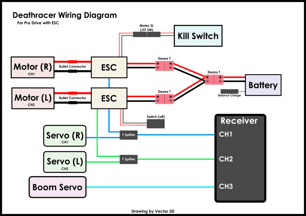
Wiring Diagram
Full Deathracer wiring diagram
Troubleshooting
One side of the tracks runs slower than the other.
Reverse esc-motor connection and reverse the channel in the transmitter.
Switch has no effect on the operation of the Deathracer
Second ESC switch is set to on, turn it off.
Channels aren’t mixing, they are independent of each other.
Probably didn’t save, hold cancel to save and ensure they are enabled.
One track going in the wrong direction.
Check connection orientation. The ECSs have a faster forward then reverse, they need to both have the forward going in the same direction. This is done by the esc so the output wires from the ESC will need to be switched for one of the motors. You might also notice that one drive starts moving before the other, the one that responds first is going forward, the other is going backwards.
Too powerful to control
I found that the motors were a bit overpowered for this vehicle and without highly skilled driving keeping it under control was difficult at times. I used the control limits on the transmitter to set the max and min positions to around +/-30% respectively and then you can increase as you get more comfortable with driving.
I don’t like how the bludger is controlled with throttle
This is personal preference, but you can change it easily simply by plugging the large servo into channel 4 on the receiver instead, this will then use the remaining channer on the sticks for bludger control.